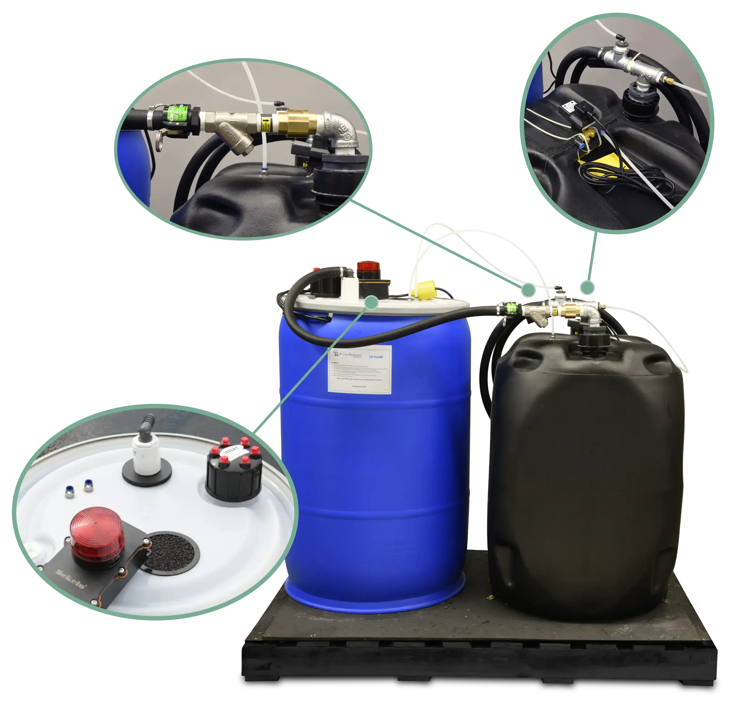

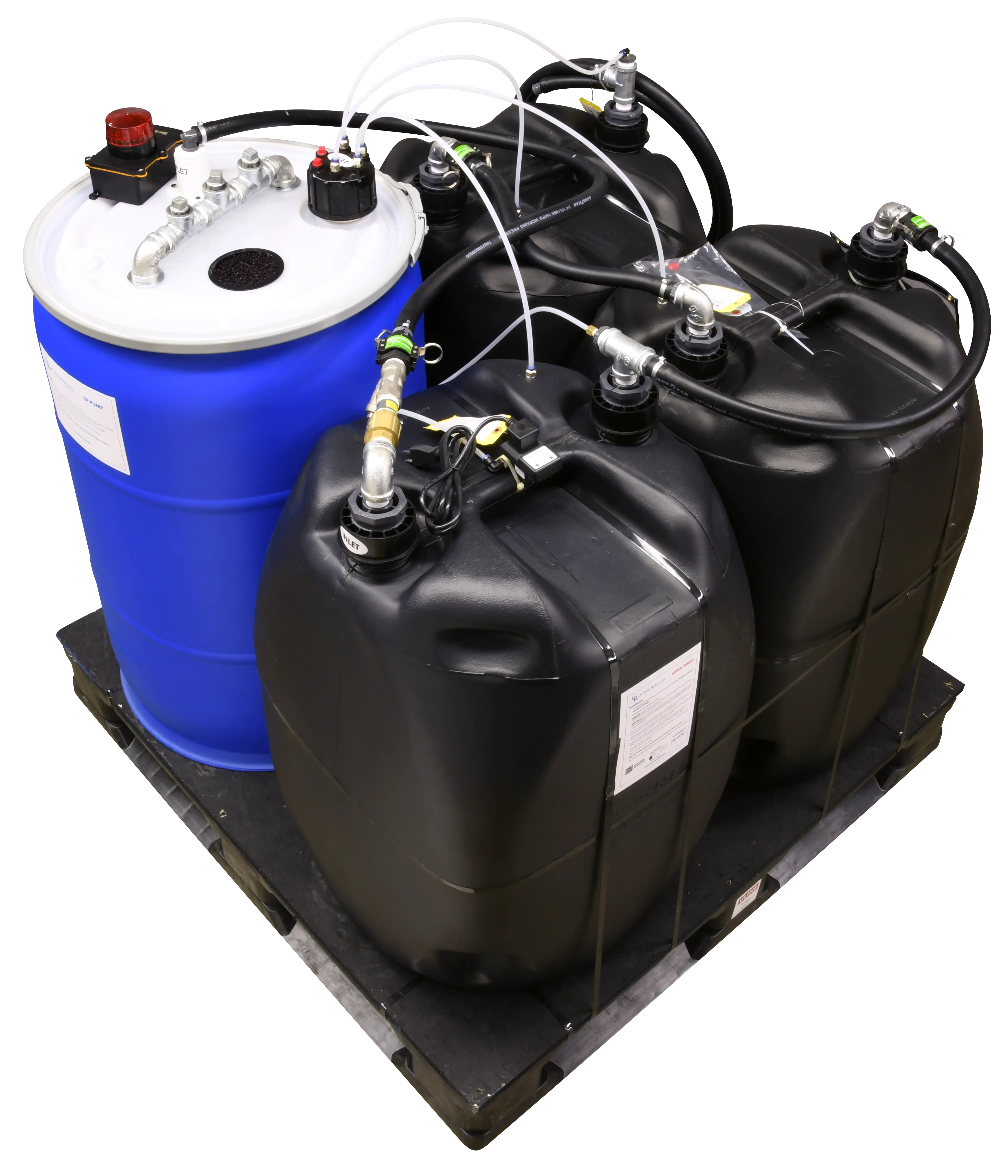
Anti-siphon Line
Any excess pressure in the system is returned to the pump
Outlet Hose
10 ppm or less of filtered condensate exits to sanitary or floor drain
Timer Drain
Sends regular bursts of air through the media bed to maintain optimal oil-water separation efficiency
Cam Lock
Quick connect cam lock for easy and secure pump connection to the unit
Flow Reducer
Regulates higher water flow from pump down to 10 GPM to restrict condensate intake
Y-Strainer
Inline filter for catching large particles from compressor or other downstream devices. The removable and reusable screen should be checked and rinsed every 1–3 months
Decompression Lines
Relieves any excess pressure build-up preventing air lock
Dual Pump System
Secondary pump takes over if primary pump fails. Audible and visual alarm signals
Pump Line
Condensate exits the SP-Pump and enters the Super-Pak via the Y-Strainer
Decompression Line Connections
Connect decompression lines here to relieve excess pressure build-up preventing air lock
Vent
Pressure is decompressed and vented before entering the OWS unit, preventing air locks
Condensate Inlet
Replace red caps with supplied push-to-connect fittings and insert compressor lines
Alarm
Signals if primary pump fails and secondary pump takes over
Small footprint for large HP systems
System capacity functions on ALL compressor lubricants
Ships from factory pre-plumbed, primed and leak tested
System monitoring for timely change out
No exposure to black mold, bacteria or E. coli
No maintenance or messy bag change-outs
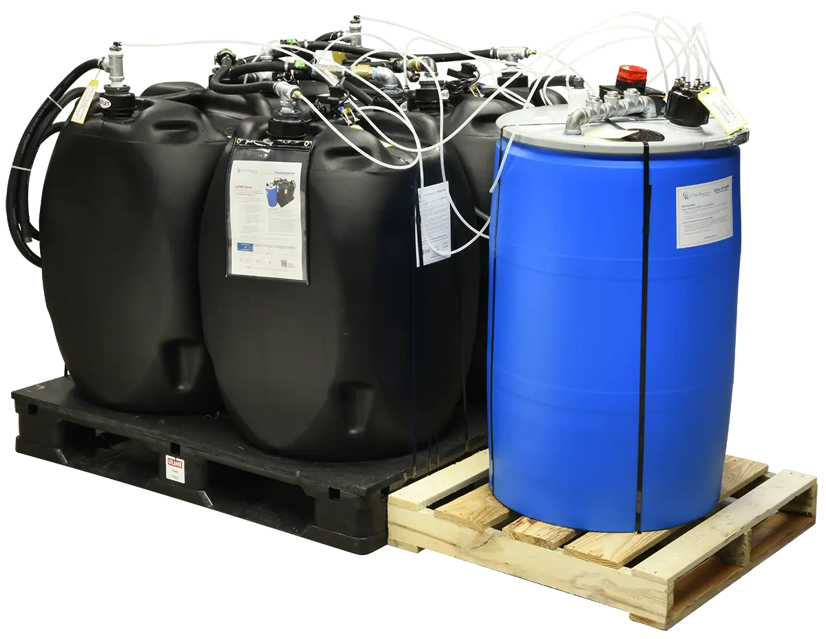
Super-PAK Series
Clean Resources Super-PAK Oil-Water Separator series sets the bar for condensate management on large, compressed air systems. Whether you’re running 200 HP or 2000 HP, there’s a Super-PAK configuration to match your system or compressor room. Standard systems are designed for 4,000 – 10,000 CFM applications.
Using our proprietary alumina silicate substrate media, the Super-PAK oil-water separator beds adsorb ALL compressor-based lubricants, including silicone, polyalkylene glycol (PAGs), and food grade. No other oil-water separator company has the data to make this claim.
Have more than one compressor using different types of lubricants? No problem. All Clean Resources products can handle multiple systems connected simultaneously with just one unit. When spent, all Super series units can be returned to one of our sites for recycling. You will find the disposal form at recycleoilsep.com and follow the instructions.
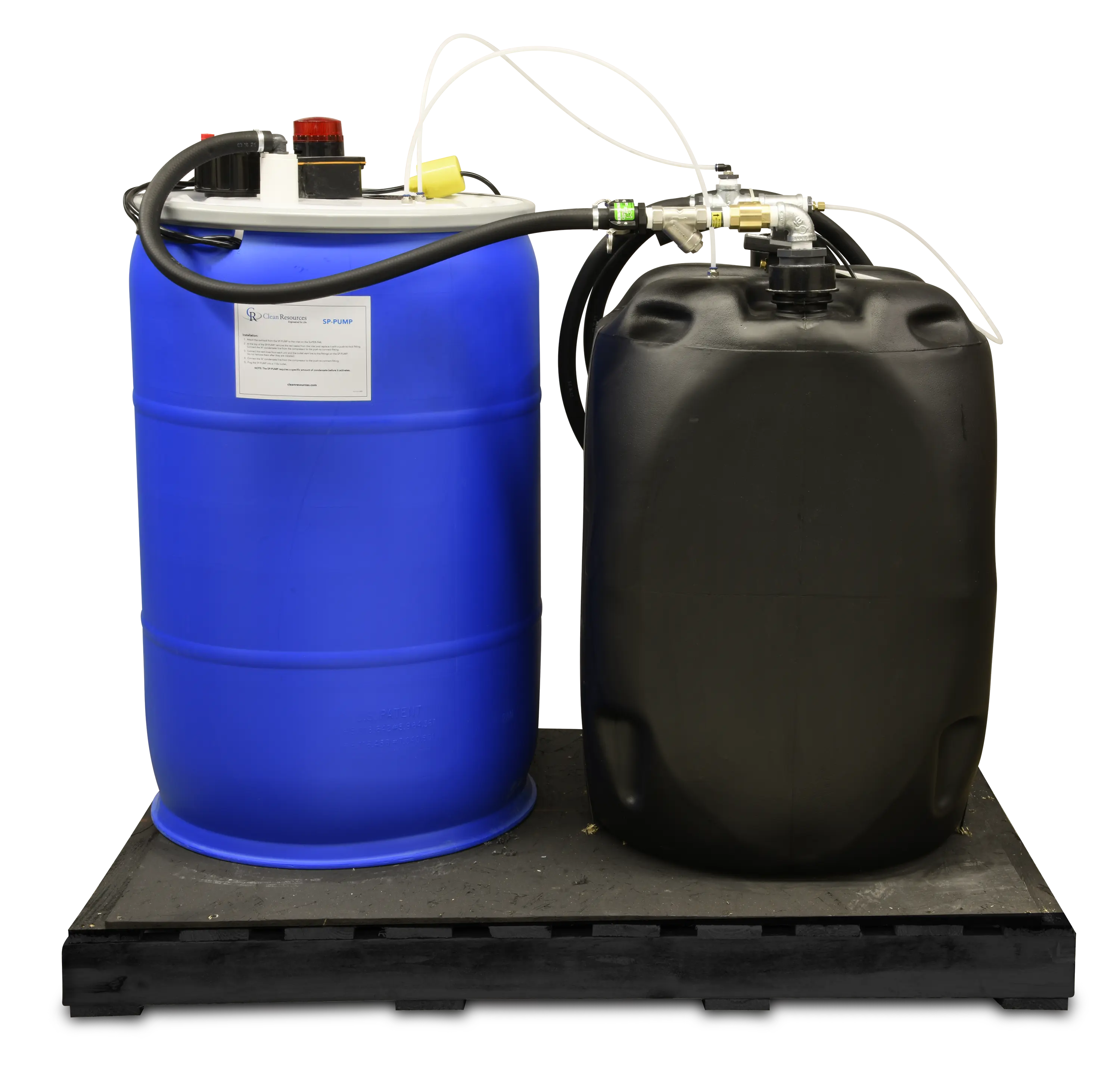
Super-PAK 1
The Super-PAK 1 is designed for systems up to 1,200 HP.
Part Number: F10250
| Super Unit | Width (in) | Depth (in) | Height (in) | Weight (lbs) |
|---|---|---|---|---|
| 1 | 40 | 48 | 69 | 750 |
| HP | ACFM | Unit Life in Hours†‡ | Est. Hrs/Yr |
|---|---|---|---|
| 150 | 750 | 24,000 | 8,000 |
| 200 | 1,000 | 18,000 | 8,000 |
| 250 | 1,250 | 15,000 | 8,000 |
| 300 | 1,500 | 11,000 | 8,000 |
| 350 | 1,750 | 10,000 | 8,000 |
| 400 | 2,000 | 8,000 | 8,000 |
| 450 | 2,250 | 8,000 | 8,000 |
| 500 | 2,500 | 7,000 | 8,000 |
| 600 | 3,000 | 6,000 | 8,000 |
| 800 | 4,000 | 5,000 | 8,000 |
| 1,000 | 5,000 | 4,000 | 8,000 |
† Unit life numbers in this chart assume rotary screw compressors with 2 ppm oil carryover running 8,000 hrs/yr. Unit life may vary due to differences in air compressor oil consumption rates, age, and maintenance of compressor. For use with reciprocating compressors, consult factory to calculate unit life.
ROTARY SCREW COMPRESSORS (2 ppm carryover)
Unit Life: [hours from above] x [CF from below]
Example: Super-Pak 3 at 450 hp running 8,000 hrs/yr
Unit Life: 24,000 x 1 = 24,000 hours‡
‡ To calculate the unit life in months: [Unit Life] / 8,000 * 12
| Hrs/yr runtime | 8,000 | 6,000 | 4,000 | 2,000 |
|---|---|---|---|---|
| Life Correction Factor (CF) | 1 | 1.33 | 2 | 4 |
| Sizes and Specifications | |
|---|---|
| Inlets | Three ¾″ |
| Maximum inlet pressure | 175 psi |
| Timer drain power requirements | 120 Volt, 20 Amp |
| Dual pump & alarm power requirements | Three 120 Volt, 20 Amp |
| Anti-siphon line | ¼″ |
| Decompression line | ¼″ |
| Timer drain in/out poly tube | ¼″ |
| Pump line | ¾″ |
| Drum-connecting hoses | ¾″ |
| Discharge hose | ¾″ |
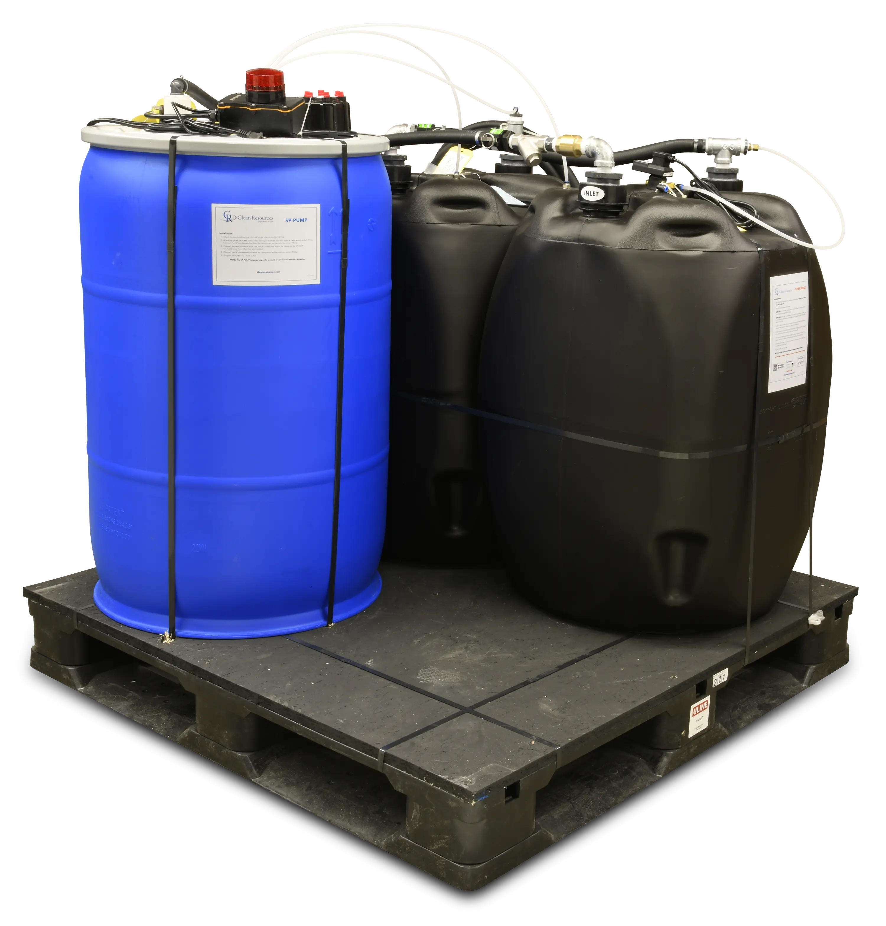
Super-PAK 2
The Super-PAK 2 is designed for systems from 200 HP to 1,800 HP.
Part Number: F10251
| Super Unit | Width (in) | Depth (in) | Height (in) | Weight (lbs) |
|---|---|---|---|---|
| 2 | 40 | 48 | 69 | 1,500 |
| HP | ACFM | Unit Life in Hours†‡ | Est. Hrs/Yr |
|---|---|---|---|
| 200 | 1,000 | 25,000 | 8,000 |
| 250 | 1,250 | 20,000 | 8,000 |
| 300 | 1,500 | 16,000 | 8,000 |
| 350 | 1,750 | 13,000 | 8,000 |
| 400 | 2,000 | 12,000 | 8,000 |
| 450 | 2,250 | 11,000 | 8,000 |
| 500 | 2,500 | 10,000 | 8,000 |
| 600 | 3,000 | 8,000 | 8,000 |
| 800 | 4,000 | 6,000 | 8,000 |
| 1,000 | 5,000 | 5,000 | 8,000 |
| 1,200 | 6,000 | 4,000 | 8,000 |
| 1,400 | 7,000 | 4,000 | 8,000 |
† Unit life numbers in this chart assume rotary screw compressors with 2 ppm oil carryover running 8,000 hrs/yr. Unit life may vary due to differences in air compressor oil consumption rates, age, and maintenance of compressor. For use with reciprocating compressors, consult factory to calculate unit life.
ROTARY SCREW COMPRESSORS (2 ppm carryover)
Unit Life: [hours from above] x [CF from below]
Example: Super-Pak 3 at 450 hp running 8,000 hrs/yr
Unit Life: 24,000 x 1 = 24,000 hours‡
‡ To calculate the unit life in months: [Unit Life] / 8,000 * 12
| Hrs/yr runtime | 8,000 | 6,000 | 4,000 | 2,000 |
|---|---|---|---|---|
| Life Correction Factor (CF) | 1 | 1.33 | 2 | 4 |
| Sizes and Specifications | |
|---|---|
| Inlets | Three ¾″ |
| Maximum inlet pressure | 175 psi |
| Timer drain power requirements | 120 Volt, 20 Amp |
| Dual pump & alarm power requirements | Three 120 Volt, 20 Amp |
| Anti-siphon line | ¼″ |
| Decompression line | ¼″ |
| Timer drain in/out poly tube | ¼″ |
| Pump line | ¾″ |
| Drum-connecting hoses | ¾″ |
| Discharge hose | ¾″ |
Super-PAK 3
The Super-PAK 3 is designed for high-flow systems from 300 HP to 2,000 HP.
Part Number: F10252
| Super Unit | Width (in) | Depth (in) | Height (in) | Weight (lbs) |
|---|---|---|---|---|
| 3 | 48 | 48 | 69 | 2,250 |
| HP | ACFM | Unit Life in Hours†‡ | Est. Hrs/Yr |
|---|---|---|---|
| 300 | 1,500 | 27,000 | 8,000 |
| 350 | 1,750 | 23,000 | 8,000 |
| 400 | 2,000 | 20,000 | 8,000 |
| 450 | 2,250 | 19,000 | 8,000 |
| 500 | 2,500 | 17,000 | 8,000 |
| 600 | 3,000 | 15,000 | 8,000 |
| 800 | 4,000 | 11,000 | 8,000 |
| 1,000 | 5,000 | 9,000 | 8,000 |
| 1,200 | 6,000 | 7,000 | 8,000 |
| 1,400 | 7,000 | 6,000 | 8,000 |
| 1,600 | 8,000 | 5,000 | 8,000 |
| 1,800 | 9,000 | 5,000 | 8,000 |
| 2,000 | 10,000 | 4,000 | 8,000 |
† Unit life numbers in this chart assume rotary screw compressors with 2 ppm oil carryover running 8,000 hrs/yr. Unit life may vary due to differences in air compressor oil consumption rates, age, and maintenance of compressor. For use with reciprocating compressors, consult factory to calculate unit life.
ROTARY SCREW COMPRESSORS (2 ppm carryover)
Unit Life: [hours from above] x [CF from below]
Example: Super-Pak 3 at 450 hp running 8,000 hrs/yr
Unit Life: 24,000 x 1 = 24,000 hours‡
‡ To calculate the unit life in months: [Unit Life] / 8,000 * 12
| Hrs/yr runtime | 8,000 | 6,000 | 4,000 | 2,000 |
|---|---|---|---|---|
| Life Correction Factor (CF) | 1 | 1.33 | 2 | 4 |
| Sizes and Specifications | |
|---|---|
| Inlets | Three ¾″ |
| Maximum inlet pressure | 175 psi |
| Timer drain power requirements | 120 Volt, 20 Amp |
| Dual pump & alarm power requirements | Three 120 Volt, 20 Amp |
| Anti-siphon line | ¼″ |
| Decompression line | ¼″ |
| Timer drain in/out poly tube | ¼″ |
| Pump line | ¾″ |
| Drum-connecting hoses | ¾″ |
| Discharge hose | ¾″ |
Super-PAK 4
The Super-PAK 4 is our largest OWS, designed for high-flow systems 450 HP and up.
Part Number: F10253
| Super Unit | Width (in) | Depth (in) | Height (in) | Weight (lbs) |
|---|---|---|---|---|
| 4 | 48 | 48 | 69 | 3,000 |
| HP | ACFM | Unit Life in Hours†‡ | Est. Hrs/Yr |
|---|---|---|---|
| 450 | 2,250 | 26,000 | 8,000 |
| 500 | 2,500 | 25,000 | 8,000 |
| 600 | 3,000 | 21,000 | 8,000 |
| 800 | 4,000 | 15,000 | 8,000 |
| 1,000 | 5,000 | 12,000 | 8,000 |
| 1,200 | 6,000 | 11,000 | 8,000 |
| 1,400 | 7,000 | 9,000 | 8,000 |
| 1,600 | 8,000 | 8,000 | 8,000 |
| 1,800 | 9,000 | 7,000 | 8,000 |
| 2,000 | 10,000 | 6,000 | 8,000 |
† Unit life numbers in this chart assume rotary screw compressors with 2 ppm oil carryover running 8,000 hrs/yr. Unit life may vary due to differences in air compressor oil consumption rates, age, and maintenance of compressor. For use with reciprocating compressors, consult factory to calculate unit life.
ROTARY SCREW COMPRESSORS (2 ppm carryover)
Unit Life: [hours from above] x [CF from below]
Example: Super-Pak 3 at 450 hp running 8,000 hrs/yr
Unit Life: 24,000 x 1 = 24,000 hours‡
‡ To calculate the unit life in months: [Unit Life] / 8,000 * 12
| Hrs/yr runtime | 8,000 | 6,000 | 4,000 | 2,000 |
|---|---|---|---|---|
| Life Correction Factor (CF) | 1 | 1.33 | 2 | 4 |
| Sizes and Specifications | |
|---|---|
| Inlets | Three ¾″ |
| Maximum inlet pressure | 175 psi |
| Timer drain power requirements | 120 Volt, 20 Amp |
| Dual pump & alarm power requirements | Three 120 Volt, 20 Amp |
| Anti-siphon line | ¼″ |
| Decompression line | ¼″ |
| Timer drain in/out poly tube | ¼″ |
| Pump line | ¾″ |
| Drum-connecting hoses | ¾″ |
| Discharge hose | ¾″ |