EHD Series Air Dryers
In today’s demanding industrial environment, where moisture can wreak havoc on equipment and processes, it is crucial to invest in cutting-edge technology that safeguards your operations. That’s where Next Air & Gas Heated Regenerative Desiccant Dryers come in.
Designed with globality in mind and built to excel, our regenerative dryers are the ultimate solution for moisture control in compressed air systems. Whether you operate in manufacturing, food processing, pharmaceuticals, or any other industry relying on compressed air, our dryers provide a vital shield against the damaging effects of moisture.
Our dryer series uses fully pneumatic stainless steel actuator valves rather than dated shuttle valves. This allows for independence of flow and pressure. With some dryers being only region-specific we made sure that all dryers produced by Next Air & Gas are certified with ASME, CRN, UL, CUL certification. With industry standards of design pressure being up to 150 psig, we thought it best to invest in the technical advantages and manufacture our pressure vessels to run at 200 psig (80–1,600 CFM) as standard.
Investing in our compressed air desiccant air dryers means investing in reliability, productivity, and peace of mind. With our expertise and commitment to excellence, we provide you with the tools to achieve superior air quality and protect your valuable equipment and processes.
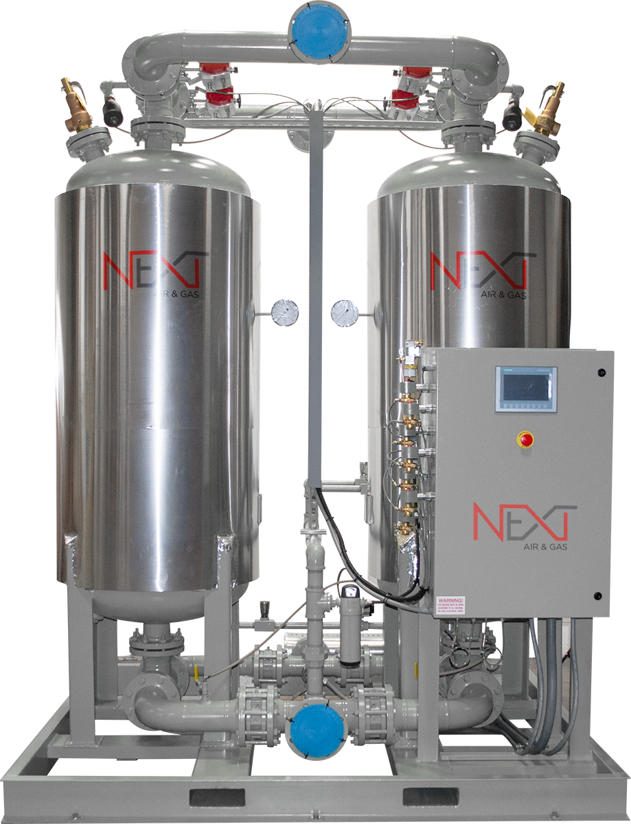
EHD 500 – 10000
In Next Air & Gas External Heater models, purge air is heated then passed over the bed to regenerate it. These are custom designed products, and we provide design and engineering assistance as needed to manufacture these unique systems. Should you need guidance determining which type of dryer works best for your operation, our experts are happy to analyze and make recommendations.
| EHD Unit | Inlet Flow Capacity (cfm) |
Port Size | Weight (lbs) | Dimensions (in) (W × D × H) |
|---|---|---|---|---|
| EHD-200 | 200 | 1" NPT | 950 | 42×38×89 |
| EHD-250 | 250 | 1½" NPT | 1,100 | 43×43×90 |
| EHD-300 | 300 | 1½" NPT | 1,250 | 43×43×90 |
| EHD-400 | 400 | 2" NPT | 1,500 | 47×45×92 |
| EHD-500 | 500 | 2" NPT | 1,600 | 47×45×92 |
| EHD-600 | 600 | 2" NPT | 2,100 | 47×45×92 |
| EHD-800 | 800 | 3" FLG | 2,500 | 80×60×92 |
| EHD-900 | 900 | 3" FLG | 2,800 | 80×60×95 |
| EHD-1000 | 1,000 | 3" FLG | 4,100 | 80×60×95 |
| EHD-1250 | 1,250 | 3" FLG | 4,700 | 80×60×95 |
| EHD-1500 | 1,500 | 3" FLG | 4,900 | 80×60×95 |
| EHD-2000 | 2000 | 4" FLG | 5,300 | 85×68×113 |
| EHD-2500 | 2,500 | 4" FLG | 6,200 | 85×68×113 |
| EHD-3000 | 3,000 | 6" FLG | 7,600 | 125×82×134 |
| EHD-3500 | 3,500 | 6" FLG | 8,300 | 125×82×134 |
Inlet Flow Capacity numbers in this chart assume operating pressure of 100 psig and inlet air temperature of 100° F. Apply correction factors from the tables below to determine capacity based on pressure and temperature variance.
Example: EHD-1000 at 150 psig and 90° F
Inlet Flow Capacity: 1,000 × 1.20 × 1.06 = 1,272 cfm
Capacity Correction Factors for Differing Operating Pressure
| Operating Pressure (psig) | Correction Factor (CF) |
|---|---|
| 50 | 0.56 |
| 60 | 0.65 |
| 70 | 0.74 |
| 80 | 0.83 |
| 90 | 0.91 |
| 100 | 1.00 |
| 110 | 1.04 |
| 120 | 1.08 |
| 130 | 1.12 |
| 140 | 1.16 |
| 150 | 1.20 |
| 175 | 1.29 |
| 200 | 1.37 |
| 225 | 1.45 |
| 250 | 1.52 |
Capacity Correction Factors for Differing Inlet Air Temperatures
| ° F | Correction Factor (CF) |
|---|---|
| 70 | 1.12 |
| 80 | 1.10 |
| 90 | 1.06 |
| 100 | 1.00 |
| 105 | 0.93 |
| 110 | 0.86 |
| 115 | 0.80 |
| 120 | 0.75 |