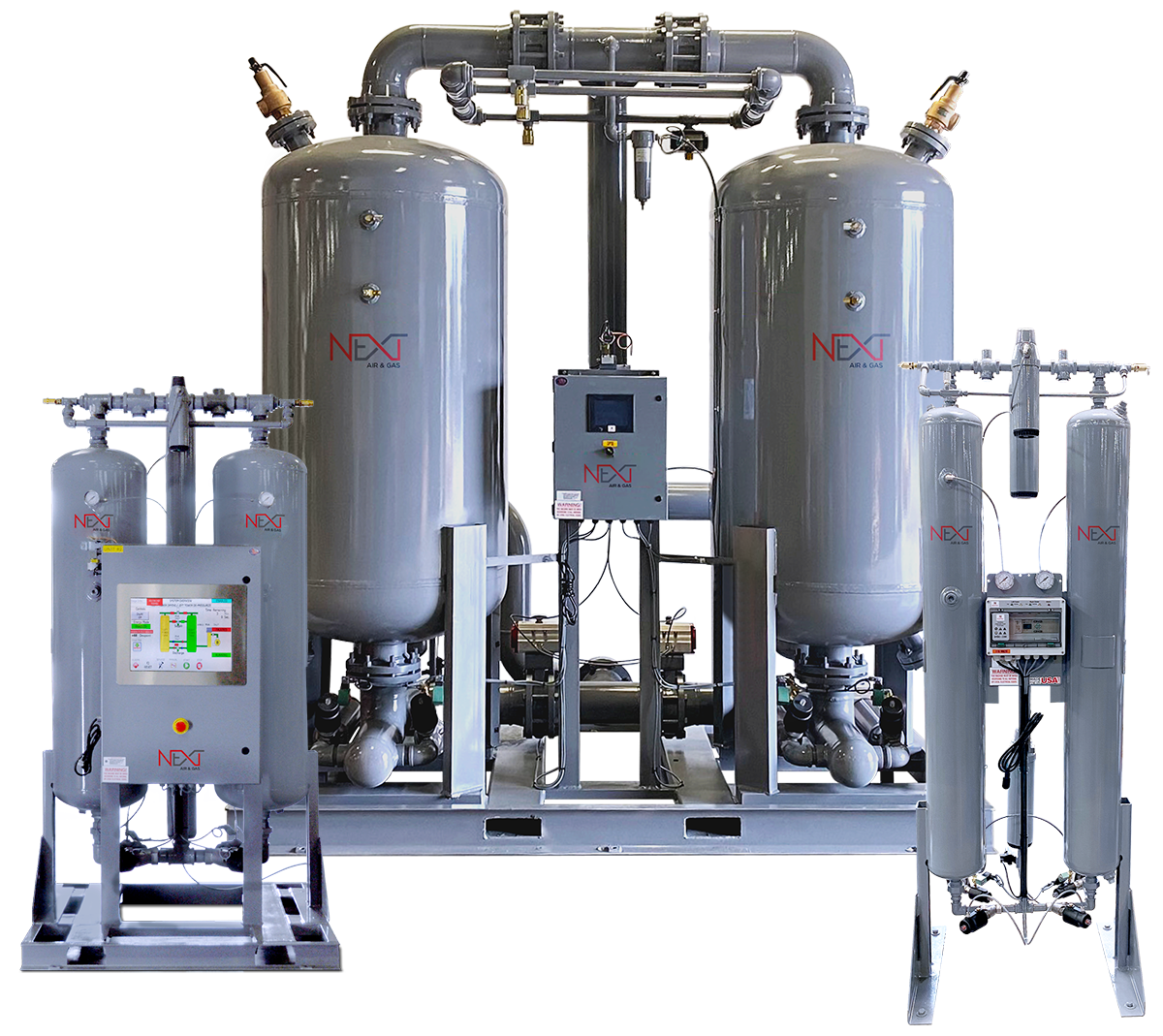
CHD Series Air Dryers
In today’s demanding industrial environment, where moisture can wreak havoc on equipment and processes, it is crucial to invest in cutting-edge technology that safeguards your operations. That’s where Next Air’s CHD Series heatless dryers come in.
Next Air & Gas regenerative dryers are the ultimate solution to eliminate moisture control in compressed air systems. Whether you operate in manufacturing, food processing, pharmaceuticals, or any other industry relying on compressed air, our dryers provide a vital shield against the damaging effects of moisture.
Our dryer series uses fully pneumatic stainless steel actuator valves rather than dated shuttle valves, allowing for flow and pressure independence. With some dryers being only region-specific, we ensured that all dryers produced by Next Air were certified with ASME, CRN, UL, and CUL certification. With industry standards of design pressure being up to 150 psig, we thought it best to invest in the technical advantages and manufacture our pressure vessels to run at 200 psig (40–1,600 CFM) as standard.
Investing in our desiccant regenerative dryers means investing in reliability, productivity, and peace of mind. With our expertise and commitment to excellence, we provide you with the tools to achieve superior air quality and protect your valuable equipment and processes.
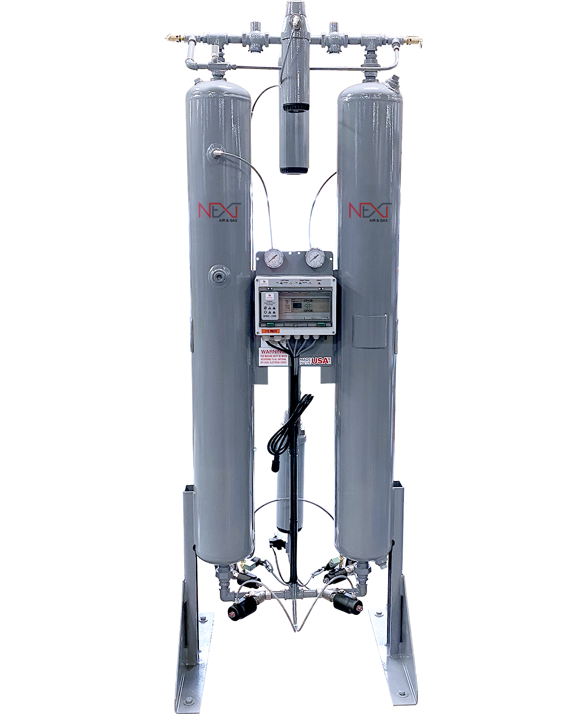
CHD 40 – 5000
The Next Air & Gas twin tower design allows for continuous adsorption of water vapor from compressed air by using high-quality, domestically made desiccant with high crush strength and a high surface/volume ratio. Drying is accomplished by passing compressed air through one desiccant bed adsorbing moisture while the other is being simultaneously regenerated with the expanded purge air.
| CHD Unit | Inlet Flow Capacity (cfm) |
Port Size | Weight (lbs) | Dimensions (in) (W × D × H) |
|---|---|---|---|---|
| CHD-40 | 40 | ¾" NPT | 300 | 30×24×63 |
| CHD-60 | 60 | ¾" NPT | 360 | 30×24×67 |
| CHD-80 | 80 | ¾" NPT | 450 | 30×24×84 |
| CHD-100 | 100 | 1" NPT | 450 | 30×24×84 |
| CHD-125 | 125 | 1" NPT | 450 | 30×24×84 |
| CHD-150 | 150 | 1" NPT | 650 | 34×24×85 |
| CHD-200 | 200 | 1" NPT | 650 | 34×24×85 |
| CHD-250 | 250 | 1½" NPT | 675 | 39×24×86 |
| CHD-300 | 300 | 1½" NPT | 1,250 | 39×24×86 |
| CHD-400 | 400 | 2" NPT | 1,250 | 44×26×87 |
| CHD-500 | 500 | 2" NPT | 1,250 | 47×26×88 |
| CHD-600 | 600 | 2" NPT | 2,900 | 47×26×88 |
| CHD-800 | 800 | 3" FLG | 2,900 | 66×40×97 |
| CHD-1000 | 1,000 | 3" FLG | 3,900 | 66×40×97 |
| CHD-1250 | 1,250 | 3" FLG | 3,900 | 66×40×97 |
| CHD-1500 | 1,500 | 3" FLG | 4,985 | 84×59×115 |
| CHD-2000 | 2,000 | 4" FLG | 4,985 | 84×59×115 |
| CHD-2500 | 2,500 | 4" FLG | 7,900 | 84×59×115 |
| CHD-3000 | 3,000 | 6" FLG | 7,900 | 103×70×137 |
| CHD-3500 | 3500 | 6" FLG | 9,500 | Contact Factory |
| CHD-4000 | 4,000 | 6" FLG | 9,500 | Contact Factory |
| CHD-4500 | 4,500 | 6" FLG | 12,500 | Contact Factory |
| CHD-5000 | 5,000 | 6" FLG | 12,500 | Contact Factory |
Inlet Flow Capacity numbers in this chart assume operating pressure of 100 psig and inlet air temperature of 100° F. Apply correction factors from the tables below to determine capacity based on pressure and temperature variance.
Example: CHD-100 at 150 psig and 90° F
Inlet Flow Capacity: 100 × 1.20 × 1.06 = 127.2 cfm
Capacity Correction Factors for Differing Operating Pressure
| Operating Pressure (psig) | Correction Factor (CF) |
|---|---|
| 50 | 0.56 |
| 60 | 0.65 |
| 70 | 0.74 |
| 80 | 0.83 |
| 90 | 0.91 |
| 100 | 1.00 |
| 110 | 1.04 |
| 120 | 1.08 |
| 130 | 1.12 |
| 140 | 1.16 |
| 150 | 1.20 |
| 175 | 1.29 |
| 200 | 1.37 |
| 225 | 1.45 |
| 250 | 1.52 |
Capacity Correction Factors for Differing Inlet Air Temperatures
| ° F | Correction Factor (CF) |
|---|---|
| 70 | 1.12 |
| 80 | 1.10 |
| 90 | 1.06 |
| 100 | 1.00 |
| 105 | 0.93 |
| 110 | 0.86 |
| 115 | 0.80 |
| 120 | 0.75 |