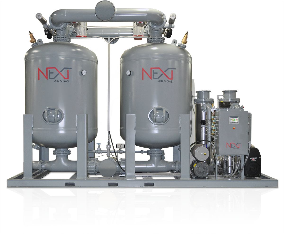
BPD Series Air Dryers
In today’s demanding industrial environment, where moisture can wreak havoc on equipment and processes, it is crucial to invest in cutting-edge technology that safeguards your operations. That’s where Next Air & Gas Heated Regenerative Desiccant Dryers come in.
Designed with globality in mind and built to excel, our regenerative dryers are the ultimate solution for moisture control in compressed air systems. Whether you operate in manufacturing, food processing, pharmaceuticals, or any other industry relying on compressed air, our dryers provide a vital shield against the damaging effects of moisture.
Our dryer series uses fully pneumatic stainless steel actuator valves rather than dated shuttle valves. This allows for independence of flow and pressure. With some dryers being only region-specific we made sure that all dryers produced by Next Air & Gas are certified with ASME, CRN, UL, CUL certification. With industry standards of design pressure being up to 150 psig, we thought it best to invest in the technical advantages and manufacture our pressure vessels to run at 200 psig (80–1,600 CFM) as standard.
Investing in our compressed air desiccant air dryers means investing in reliability, productivity, and peace of mind. With our expertise and commitment to excellence, we provide you with the tools to achieve superior air quality and protect your valuable equipment and processes.
BPD 500 – 10000
In Next Air & Gas Blower Purge air dryers, an automatic system using a centrifugal blower and a high-efficiency heater pulls in ambient air and passes it through the heater. This eliminates the need to use valuable compressed dry air for desiccant regeneration. Instead, more compressed air goes to plant operations. The hot air stream from the blower flows opposite to the drying flow direction. Hot air above 400° F regenerates the moisture-laden desiccant bed and strips it completely of moisture. Our advanced control system monitors the dewpoint and adjusts the heating/regeneration accordingly, thereby providing significant energy savings. The heater circuit is completely insulated, ensuring maximum heating efficiency.
| BPD Unit | Inlet Flow Capacity (cfm) |
Port Size | Weight (lbs) | Dimensions (in) (W × D × H) |
|---|---|---|---|---|
| BPD-500 | 500 | 2" NPT | 2,500 | 71×45×92 |
| BPD-650 | 650 | 2" NPT | 2,750 | 71×45×92 |
| BPD-800 | 800 | 3" FLG | 4,100 | 93×60×95 |
| BPD-1000 | 1,000 | 3" FLG | 4,500 | 93×60×95 |
| BPD-1250 | 1,250 | 3" FLG | 8,200 | 93×60×97 |
| BPD-1500 | 1,500 | 3" FLG | 8,200 | 93×60×97 |
| BPD-2000 | 2,000 | 4" FLG | 9,800 | 106×65×114 |
| BPD-2500 | 2,500 | 4" FLG | 15,000 | 106×82×114 |
| BPD-3000 | 3,000 | 6" FLG | 19,000 | 130×82×134 |
| BPD-3500 | 3,500 | 6" FLG | 19,000 | 130×82×134 |
| BPD-4000 | 4,000 | 6" FLG | 28,000 | 130×82×134 |
| BPD-5000 | 5,000 | 6" FLG | Contact Factory | 130×82×134 |
| BPD-6000 | 6,000 | 6" FLG | Contact Factory | Contact Factory |
| BPD-7000 | 7,000 | 8" FLG | Contact Factory | Contact Factory |
| BPD-8000 | 8,000 | 8" FLG | Contact Factory | Contact Factory |
| BPD-9000 | 9,000 | 10" FLG | Contact Factory | Contact Factory |
| BPD-10000 | 10,000 | 10" FLG | Contact Factory | Contact Factory |
Inlet Flow Capacity numbers in this chart assume operating pressure of 100 psig and inlet air temperature of 100° F. Apply correction factors from the tables below to determine capacity based on pressure and temperature variance.
Example: BPD-1000 at 150 psig and 90° F
Inlet Flow Capacity: 1,000 × 1.20 × 1.06 = 1,272 cfm
Capacity Correction Factors for Differing Operating Pressure
| Operating Pressure (psig) | Correction Factor (CF) |
|---|---|
| 50 | 0.56 |
| 60 | 0.65 |
| 70 | 0.74 |
| 80 | 0.83 |
| 90 | 0.91 |
| 100 | 1.00 |
| 110 | 1.04 |
| 120 | 1.08 |
| 130 | 1.12 |
| 140 | 1.16 |
| 150 | 1.20 |
| 175 | 1.29 |
| 200 | 1.37 |
| 225 | 1.45 |
| 250 | 1.52 |
Capacity Correction Factors for Differing Inlet Air Temperatures
| ° F | Correction Factor (CF) |
|---|---|
| 70 | 1.12 |
| 80 | 1.10 |
| 90 | 1.06 |
| 100 | 1.00 |
| 105 | 0.93 |
| 110 | 0.86 |
| 115 | 0.80 |
| 120 | 0.75 |